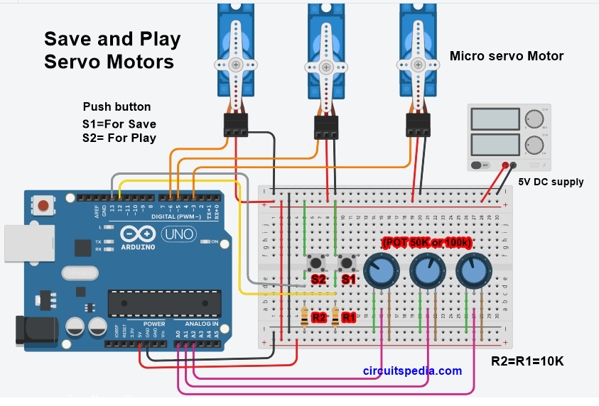
The precise rotation of a corner by a servo in response to certain digital signals represents one of the most used features in all fields of robotics. Although this movement does not seem considerable, it can be more than enough to manoeuvre a robot, raise and lower the legs, rotate a sensor that has to examine what surrounds them and much more. Although it is possible to configure an R/C servo to rotate continuously, the fundamental use of a servo is to achieve an accurate position of the motor shaft, with movements in the range between 90 ° and 180 ‘. It is easy to deduce that servomotors are generally designed to perform a partial rotation rather than set a continuous rotary motion, as in the case of a continuous or stepping motor. Each type has their benefits and drawbacks so you will want to consider whichever type works best for your servo project. When the potentiometer reaches the desired position, the control circuit turns off the motor. Continuous rotation servos work well as drive motors or other applications where you need to control the speed and direction of a motor with just a few wires. The position of the potentiometer shaft indicates a measurement of the position of the servo motor shaft.

This activates the motor which, through a series of gears, is connected to the potentiometer. Only two data pins (SDA & SCL in addition to the power pins GND & 5V) are required to drive the.
#DRIVE SERVO MOTOR ARDUINO HOW TO#
The below example shows how to move the servo motor from 30° to 90° in 3 seconds. This chip handles all the motor and speed controls over I2C. In this project, you can learn how to control servo motor using serial monitor.
#DRIVE SERVO MOTOR ARDUINO CODE#
Click to enlarge image Arduino Code By using map () and millis () functions, we can control the speed of servo motor smoothly without blocking other code. To run the engine you must send a digital signal to the control circuit. Wiring Diagram This image is created using Fritzing.

That is the servo motor can be controlled by a computer using Arduino serial communication. The circuit and the motor are powered by a stabilized direct voltage, generally of value between 4.8 V and 6.0 V, although many motors are able to accept power inputs up to 7.2 V. This servo motor drive system is a USB based servo controller. The motor and potentiometer are connected to the control circuit and the combination of these three elements defines a closed-loop feedback system.

Then, go to Tools -> Port and select the COM port. Inside the servo, there is a motor, a series of gears that reduce the speed of the motor, a control circuit and a potentiometer. Go to Tools -> Board menu and select Arduino Uno from the list.


 0 kommentar(er)
